
All-in-one liquid coolers have become one of the most popular ways to cool modern desktop CPUs, particularly in gaming PCs, creator workstations and high-performance enthusiast builds.
They remove heat from the processor through a copper cold plate, transfer that heat into coolant, then push it through a radiator where larger fans can exhaust it from the case.
It is a clean and efficient approach. It also creates a thermal problem that many PC builders overlook.
When a traditional tower air cooler is installed, its fans do more than cool the CPU heatsink. They also push air across the surrounding motherboard area, including the voltage regulator modules, chokes, capacitors, memory slots and sometimes the upper M.2 heatsink.
Replace that tower cooler with a standard AIO water block and that socket-area airflow can largely disappear.
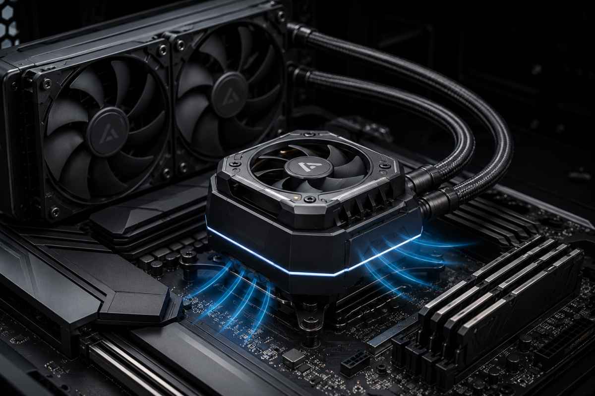
The Hybrid Socket-Flow AIO CPU Block concept is designed to solve that specific problem.
It combines a conventional liquid-cooling cold plate with a small, ducted fan built into the water block, allowing the cooler to manage both CPU heat and the stagnant air around the motherboard socket area.
The concept is not about replacing the radiator or promising dramatic CPU temperature reductions. It is about addressing a secondary but important thermal zone that standard AIOs can leave exposed.
Hybrid Flow AIO CPU Cooler Concept Design
The Problem With Conventional AIO Cooling
A standard AIO cooler is highly focused on the CPU. Heat moves from the CPU integrated heat spreader into thermal paste, then into a copper cold plate. From there, it passes through microfins into the coolant, travels to the radiator and is exhausted by radiator fans.
The thermal path is simple:
CPU IHS → thermal paste → copper cold plate → microfins → coolant → radiator → radiator fans → room airThat works well for the CPU package. But the motherboard components around the CPU socket are not always given the same attention.
A tower cooler naturally creates local airflow. Even if it is not aimed directly at the motherboard, its fan movement washes air across the socket area. VRM heatsinks, memory slots and nearby components benefit from that movement.
An AIO cooler changes the airflow pattern. The radiator fans are usually mounted at the front, top or side of the case.
The pump block sits over the CPU, but it usually does not move much air around the board. In some cases, especially compact builds or low-airflow cases, that can leave the VRM and socket area sitting in a warm pocket of air.
The Hybrid Socket-Flow AIO CPU Block is designed to restore that missing airflow.
What the Hybrid Socket-Flow AIO CPU Block Is
The Hybrid Socket-Flow AIO CPU Block is a concept water block that combines two separate thermal systems inside one housing.
The first is the familiar liquid-cooling system responsible for the CPU itself.
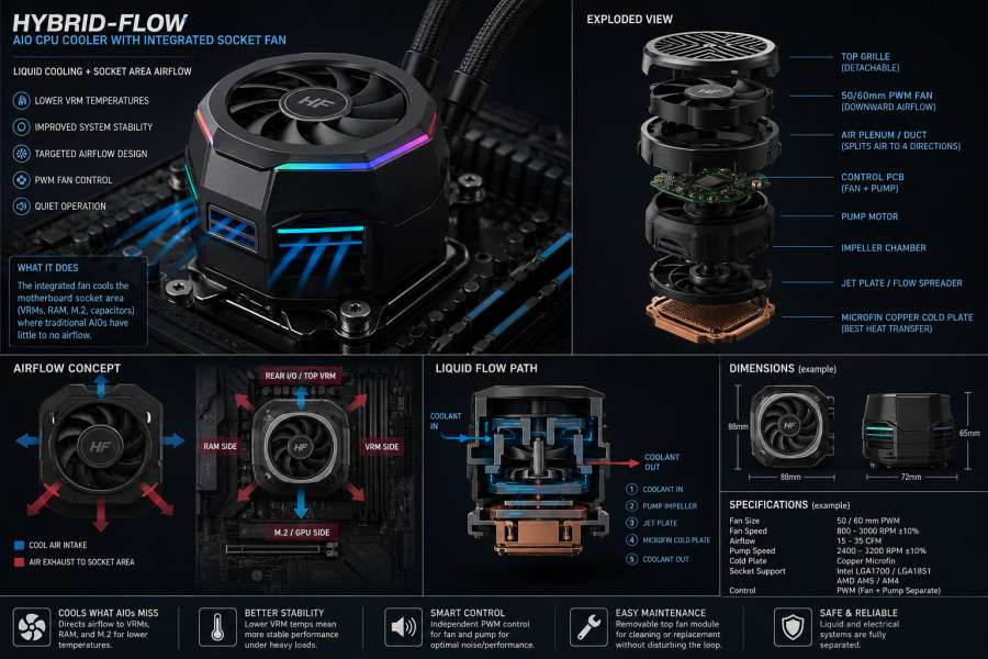
The second is an airflow system built into the top of the block, using a small PWM fan and ducted outlets to push air across the motherboard socket area.
The design brief describes the block as two separate systems sharing one outer housing: a liquid cooling system and an airflow/VRM cooling system.
The fan chamber must not interfere with the pump chamber, and the airflow should be ducted around the outside of the pump housing and down toward the motherboard.
The core design is built around this stack:
Top decorative grille / dust guard
↓
40–60 mm slim axial fan
↓
Air guide / radial duct chamber
↓
Electronics PCB / fan and pump controller
↓
Pump motor housing
↓
Pump impeller chamber
↓
Coolant inlet / outlet ports
↓
Jet plate or flow spreader
↓
Microfin copper cold plate
↓
Thermal paste
↓
CPU heat spreader
The most important rule is that the fan should not blow into the pump chamber. It should cool the motherboard area, not the liquid-cooling mechanism.
Why a Fan on the Water Block Makes Sense
The idea of adding airflow to the CPU block area is not imaginary. Some commercial AIOs already include VRM or socket-area fans. ARCTIC’s Liquid Freezer III range, for example, uses a 60 mm PWM-controlled fan for socket-area cooling when VRM cooling is insufficient, especially in cases with poor airflow.
The ARCTIC Liquid Freezer III Pro also provides separate control modes for the pump, VRM fan and radiator fans, with Australian retail listings describing “active cooling in the socket area” and a 60 mm fan in the CPU block.
Corsair has also offered an iCUE LINK AIO VRM fan module designed to provide additional airflow around the CPU socket area.
That means the general concept has precedent. The opportunity for the Hybrid Socket-Flow AIO CPU Block is not simply “put a fan on an AIO.” The stronger idea is to make that fan more useful through directional ducting, replaceable airflow inserts, serviceable fan access and smarter control logic.
In other words, the value is in the airflow engineering, not the existence of the fan alone.
How the Airflow System Would Work
The fan would sit on top of the water block, centred above the CPU socket. For a prototype, the most practical fan size would likely be 50 mm or 60 mm.
A 40 mm fan is easier to fit but may not move enough air without becoming noisy. A 70 mm fan may be more effective, but it would increase the size of the block and create more clearance challenges.
A sensible first prototype would use:
- a 50 mm or 60 mm slim PWM axial fan
- 12V operation
- 10–15 mm thickness
- hydrodynamic, magnetic or dual-ball bearing
- operating range around 800–3,000 RPM
- rubber isolation to reduce vibration
The fan should draw air from above the block and push it downward into a shaped plenum. From there, the air should be split outward into four directions.
        [Top Fan]
           ↓
   ┌─────────────────┐
   │ Air plenum zone │
   └───↓───↓───↓───↓─┘
      VRM RAM SSD IO
The airflow exits should be placed low on the block, not just near the decorative top cover. Low-mounted vents are more likely to push air across the VRM heatsinks and motherboard surface.
A top-view airflow pattern would look like this:
        Rear I/O VRMs
             ↑
             │
     ┌───────┴───────┐
RAM ←│   CPU BLOCK   │→ VRM side
     └───────┬───────┘
             │
             ↓
        M.2 / GPU side
The air duct should avoid dead-end pockets and should not blow directly into the radiator tubes. The goal is to create controlled socket-area airflow, not turbulence for the sake of appearance.
Why Ducting Is the Key Difference
A small fan spinning on top of a pump housing may look impressive, but without ducting it may do very little. It may simply stir warm air around the top of the block or create extra noise.
The Hybrid Socket-Flow AIO CPU Block concept improves the design by making the pump housing part of the airflow structure.
The fan pushes air downward into a plenum. A central deflector redirects that air outward. The airflow then travels through four shaped ducts and exits through low side vents.
A simplified side-view design would look like this:
       Fan intake
          ↓
   ┌─────────────┐
   │  top fan    │
   ├─────────────┤
   │ air plenum  │
   ├─→ → → → → →─┤  side exhaust slots
   │ pump body   │
   ├─────────────┤
   │ cold plate  │
   └─────────────┘
This gives the design a more serious engineering purpose. It is not just a pump block with a cosmetic fan. It becomes a local airflow distributor for the CPU socket area.
Liquid Cooling Path Inside the Block
The liquid side of the Hybrid Socket-Flow AIO CPU Block should remain conventional. That is important because the AIO pump, cold plate and coolant path are the most failure-sensitive parts of the design.
The recommended coolant path is:
Coolant from radiator
↓
Inlet barb
↓
Pump impeller chamber
↓
Jet plate / flow spreader
↓
Copper microfin cold plate
↓
Outlet chamber
↓
Tube back to radiator
Internally, the block could use this layout:
[Coolant In]
    ↓
[Pump Impeller]
    ↓ pressurised coolant
[Jet Plate]
    ↓
[Microfin Cold Plate]
    ↓
[Outlet Manifold]
    ↓
[Coolant Out]
The cold plate should be copper or nickel-plated copper, with a microfin field positioned over the CPU hotspot. A slightly convex contact surface may help improve mounting pressure across the CPU heat spreader.
For a precision design, a fin pitch around 0.15–0.30 mm may be appropriate if the manufacturer has access to CNC or skiving equipment.
For an early prototype, however, the liquid side should not be overcomplicated. It is better to start with an existing AIO block and design a custom fan-and-duct cap around it.
Prototype Strategy: Do Not Start With a Full Custom Pump
The easiest prototype path is not to design an entire AIO from scratch. That would require custom pump engineering, sealing, coolant compatibility, corrosion protection, pressure testing, impeller design, motor control and reliability testing.
The smarter first step is to modify the top of an existing AIO pump block.
A practical prototype could use:
Existing 240 / 280 / 360 mm AIO
+
Custom 3D-printed or CNC pump cap
+
50 / 60 mm PWM fan
+
Directional air duct outlets
+
Thermal testing
This approach proves the airflow concept without opening the sealed loop.
The first version should focus on whether the socket fan meaningfully reduces VRM and motherboard-area temperatures. If that works, a second version could move toward a fully integrated block design.
Housing Design and Materials
The block would be slightly taller than a conventional AIO pump block because it needs room for the fan, plenum and duct exits.
Suggested prototype dimensions:
| Component | Prototype Target |
|---|---|
| Block footprint | 78–90 mm square |
| Total height | 55–75 mm |
| Fan diameter | 50–60 mm |
| Fan chamber height | 12–18 mm |
| Air outlet gap | 4–8 mm |
| Tube fitting angle | Side-mounted or 45-degree swivel |
| Mounting support | AM5 / LGA1700 / LGA1851 first |
Prototype materials could include:
| Part | Suggested Material |
| Top cap | 3D-printed nylon, ABS, PETG or CNC aluminium |
| Air duct | 3D-printed nylon or PETG |
| Cold plate | Copper or nickel-plated copper |
| Pump chamber | Existing pump body, acetal/POM or PPS |
| Gasket | EPDM or silicone |
| Screws | Stainless steel |
| Fan isolation | Rubber mounts or silicone pads |
PLA should be avoided near the CPU socket because it can soften under heat over time.
Electrical Control and Fan Behaviour
A strong version of this design should expose separate control for the pump, radiator fans and block fan.
A basic wiring setup would be:
CPU_FAN header → radiator fans or fan hub tach signal
AIO_PUMP header → pump power/control
SYS_FAN or dedicated controller → block micro-fan
A more advanced version would use:
SATA power → pump and fans
PWM signal 1 → radiator fans
PWM signal 2 → pump
PWM signal 3 → block fan
USB 2.0 optional → software control
The block fan should not simply follow CPU temperature. The whole point of the design is socket-area cooling, so the fan should ideally respond to VRM or motherboard MOS temperature where available.
A simple prototype curve could look like this:
| Temperature | Block Fan Speed |
| Below 45°C | 0–30% |
| 45–60°C | 40% |
| 60–75°C | 60% |
| 75–85°C | 80% |
| Above 85°C | 100% |
If the motherboard exposes VRM temperature, that should drive the fan curve. If not, CPU package temperature or motherboard temperature can be used as a fallback.
What Performance Improvement Could Be Expected?
This design should not be marketed as a CPU temperature miracle. The radiator, pump and cold plate still do the main CPU cooling work.
A realistic expectation would be:
| Area | Expected Result |
| CPU core temperature | 0–3°C improvement, possibly no change |
| VRM temperature | 5–20°C improvement possible |
| RAM / M.2 / socket zone | 2–10°C possible |
| Stability under sustained load | Possible improvement |
| Noise | Could increase if the fan is poorly chosen |
| Dust | Likely to increase around the socket area |
The strongest technical claim would be:
The Hybrid Socket-Flow AIO CPU Block is designed to improve socket-area and VRM cooling while retaining conventional AIO CPU cooling performance.
That claim is far more credible than promising large CPU temperature reductions.
Where the Design Could Be Most Useful
The concept would be most useful in systems where the motherboard socket area suffers from limited airflow.
That includes:
- compact gaming PCs
- high-power CPU builds
- overclocked or power-unlocked systems
- workstations running long CPU-heavy tasks
- cases with low fan speeds
- front-mounted radiator setups
- systems with large GPUs dumping heat into the case
- motherboards with smaller VRM heatsinks
- builds where users want liquid cooling without losing tower-cooler airflow benefits
In a large, well-ventilated case with a premium motherboard and strong top/rear exhaust, the benefit may be smaller. In tighter systems, the gain could be more meaningful.
Engineering Risks
The concept is technically plausible, but it introduces trade-offs.
The first risk is noise. Small fans can quickly become irritating, especially if they sit behind restrictive grilles or need high RPM to move useful air. A 50 mm or 60 mm fan running at a lower speed would likely be more practical than a very small high-speed fan.
The second risk is dust. A fan blowing downward into the socket area may move dust into the motherboard’s most congested space. A removable top grille or fan cartridge would help with maintenance.
The third risk is clearance. A taller water block may interfere with RAM, VRM heatsinks, tubing, case side panels or GPU backplates. That means the block must be tested across ATX, mATX and ITX motherboard layouts.
The fourth risk is airflow misdirection. If the duct exits are poorly placed, the fan may not cool the components that need it most. The airflow path must be shaped carefully.
The fifth risk is liquid-side reliability. If the design moves beyond a cap-on-existing-AIO prototype, sealing becomes critical. The pump chamber, cold plate gasket and tube fittings must be pressure-tested and isolated from the serviceable fan module.
How the Concept Could Stand Out From Existing AIOs
Because socket-area fans already exist on some AIOs, the Hybrid Socket-Flow AIO CPU Block needs a stronger point of difference.
The best version would focus on modular airflow.
Possible improvements include:
- replaceable directional duct inserts
- AM5-specific VRM duct
- Intel LGA1700/LGA1851 duct
- RAM-side duct
- M.2-side duct
- ITX compact duct
- removable magnetic fan cartridge
- zero-RPM idle mode
- VRM-temperature-based fan curves
- coolant temperature monitoring
- tool-free fan cleaning
- lower vent exits aimed at motherboard components
That would make the design less of a novelty and more of a practical motherboard thermal-management system.
Testing the Prototype
To prove the design works, testing should compare the same AIO with the block fan off and on.
A fair test should record:
- CPU package temperature
- CPU clock speed
- CPU package power
- VRM temperature
- motherboard temperature
- RAM temperature if available
- M.2 temperature if nearby
- coolant temperature
- pump RPM
- radiator fan RPM
- block fan RPM
- ambient room temperature
- noise level
The test should include:
- idle load
- CPU-only load
- CPU and GPU combined load
- low case airflow
- front-mounted radiator
- top-mounted radiator
- fan-off versus fan-on comparison
The prototype would be worth developing further if it can lower VRM temperatures by around 8–15°C without increasing CPU temperature, creating annoying noise or causing clearance problems.
Why This Matters
CPU coolers are often judged by CPU temperature alone. That is understandable, but it is not the whole system thermal picture.
A modern PC is a dense thermal environment. The CPU, GPU, VRMs, memory, storage and chipset all compete for airflow. AIO liquid coolers are excellent at moving CPU heat to a radiator, but they do not automatically solve every heat pocket inside a case.
The Hybrid Socket-Flow AIO CPU Block takes a broader view. It treats the CPU socket as a thermal zone, not just a contact point for a cold plate.
That makes the design more relevant to real-world PC builds, especially as CPUs continue to draw high power under sustained workloads and users keep building quieter, more compact and more visually clean systems.
Final Thoughts
The Hybrid Socket-Flow AIO CPU Block is a practical concept built around a real cooling issue: standard AIO liquid coolers can reduce local airflow around the CPU socket compared with traditional tower air coolers.
By combining a conventional liquid-cooling path with a ducted, top-mounted socket fan, the design aims to cool both the CPU and the surrounding motherboard components. The CPU remains cooled by liquid. The VRMs, RAM-side socket area, M.2 zone and nearby components receive targeted airflow.
The idea should not be oversold as a world-first or a guaranteed breakthrough in CPU temperatures. Similar VRM-fan AIO designs already exist. The more credible innovation is a refined version with better ducting, modular airflow, easier fan maintenance and smarter control logic.
For a prototype, the best first step is a custom fan-and-duct cap fitted to an existing AIO pump block. That would allow the airflow system to be tested safely before investing in a fully custom pump and cold-plate assembly.
If the concept can deliver measurable VRM and socket-area temperature reductions without adding too much noise, dust or clearance complexity, it could become a meaningful evolution of the AIO cooler: not just a CPU cooler, but a more complete thermal solution for the motherboard socket area.
